Footings Page
Using Footings Tab you can design and analyze multiple footings or footing types for each column, to include single spread footing under all columns, isolated footings under each column, shaft footing, combined and strap footings under all columns.
Add new footing
First input the footing specifications for the pier structure. Each footing section must have a name and type selected before it can be designed. From the Columns list, check the column(s) you want to add a footing (or select the column(s) in the graphical display at the top of the screen. Next, input a name for the footing in the Name textbox and select the type of footing under Type: Isolated, Shaft, Combined and Strapped. Click Add. The Name will appear in the table on the screen, also information regarding the type and selected columns are displayed but are not editable. The In use option will offer two option if double clicked YES/NO which will consider or not the selected footing in the design of the pier.
Edit footing
Edit piles
When you click Edit Piles button on Isolated, Shaft, Combined or Strap footing, the Edit Piles Screen appears. Next, input the piles configuration information. Select the shape of the pile from the Type drop down list, 4 options are available: Round, Square, Chamfer, and H-steel. Depending on which shape is selected different screen parameters will appear.
| Setting | Description |
|---|---|
| Length (l) | Defines the pile length under the footing |
| Embedded length (l2) | Defines the distance that the piles are embedded into footing. |
| Diameter (w) | Defines the pile diameter if Round Pile type is selected. |
| Width (w) | Defines the pile width if Square Pile type is selected. |
| ChamferX (cx) | Defines the Chamfer if Chamfer Pile type is selected. |
| Side width (sw) | Defines the steel pile side width if H-steel Pile type is selected. |
| Side thickness (t1) | Defines the thickness of the steel heads if H-steel Pile type is selected. |
| Mid thickness (t2) | Defines the thickness of the steel strap if H-steel Pile type is selected. |
| Rotation | Defines the angle with which the piles are rotated. On this screen you can specify the piles in two ways. First option is the user input option. If you use this option, the piles are added in the table by pressing Add button found on the right side of the table, they can be easily deleted using Delete/Delete All buttons. The coordinates(X and Z) for piles are measured with the origin as shown in the figure, (0.0) represents the center of the blue circle. Repeat these steps to add additional pile locations. 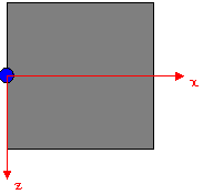
The second option allows you to specify a pattern from an already predefined Pile Pattern library, just select a pattern from the Select pattern list. You will find different pile arrangements for a certain number of piles. Program will read the pattern and show in the graphics area. If the origin of the pile group (defined in library) is at the cg of the footing, choose concentric under footing. However, if Pile group origin is not concentric with footing cg, choose the Eccentric under footing and specify the eccentricity in X and Z direction. The pile coordinates and graphics will be adjusted for the specified eccentricity. |
Edit Pattern
Selecting the Edit pattern button from the menu, will display the Pile Pattern configuration screen. This option allows you to define and manage pile pattern configurations (pile groups).
First Input a unique name of the Pile pattern, below you will find a grid based pattern type. Select number of grid lines in X and Z direction using Number of lines text box, and then specify the spacing of grid lines in two directions using Default Spacing text box. Program will recompute the grid locations and show those as X1, X2, X3… and Z1, Z2, Z3…etc. and show in the two lists. The grid based patterns must have symmetric grid placed with respect to the origin (mid) of the pattern.
You can adjust the location of grid lines at X and Z intervals. If you would like to revise, simply select the entry and modify it. Note that X1 is the distance of a grid location which is farthest from the pattern origin. X2 is the second farthest and so on. Similarly Z1 is the distance of the grid farthest in Z direction. Z2 is the second farthest and so on. These distances are shown in the plot and each grid intersection is a check box and a place where a pile can be placed. If you do not want to place a pile at a location, make sure the corresponding box is unchecked. To set/remove piles at all locations click Select/Unselect all. Click OK once all the pile locations are specified. Click cancel if you do not want to make any changes to the placement positions. After pressing OK the pattern appears in the User defined section from the Select pattern list and none selection from the same list will enable you to edit manually each pile location.